Rough-in HVAC represents the critical first phase of heating, ventilation, and air conditioning installation—the stage where all ductwork, piping, electrical connections, and mounting points are installed before walls and ceilings close in. For hydronic heating systems specifically, this means positioning boilers, running supply and return lines, placing manifolds, and roughing in radiant floor tubing or radiator connections while you still have full access to framing and structural elements.
Getting rough-in right determines whether your system operates efficiently for decades or becomes a source of constant headaches and expensive repairs. Position your main supply lines with proper slope for air elimination—typically a minimum 1/4 inch per foot rising away from the boiler. Install isolation valves at strategic locations so you can service individual zones without draining the entire system. Mark and photograph all pipe locations before drywall installation, as this documentation proves invaluable during future renovations or repairs.
The stakes are substantial. Incorrect rough-in placement means cutting into finished walls, rerouting pipes around obstacles you didn’t anticipate, or living with a system that never quite performs as designed. Many common rough-in errors stem from inadequate planning rather than poor execution—failing to coordinate with other trades, neglecting thermal expansion requirements, or rushing measurements under construction deadlines.
Whether you’re a contractor managing a custom home build or a dedicated DIYer tackling a renovation, understanding rough-in fundamentals separates successful installations from costly do-overs. This guide walks you through the complete process with practical, field-tested techniques.
What Hydronic Heating Rough-In Actually Means
The Difference Between Rough-In and Finish HVAC Work
Understanding the difference between rough-in and finish work helps you plan your project timeline and budget more effectively. Rough-in HVAC refers to everything that happens behind the walls, floors, and ceilings during the early construction phase. This includes installing main supply and return lines, running ductwork or hydronic piping through framing, positioning manifolds, and placing equipment like air handlers or boilers in their permanent locations. All this work must be completed and inspected before drywall goes up.
Finish work, on the other hand, happens after walls are closed in and painted. This phase includes installing visible components like registers, grilles, thermostats, radiators, and final equipment connections. You’ll also complete system testing, balancing, and any trim work during this stage.
The rough-in phase is absolutely critical because mistakes made here are expensive and difficult to fix once walls are sealed. That’s why inspections typically occur after rough-in completion. Getting the rough-in right means your finish work will go smoothly, and your system will operate efficiently for years to come. Plan for these two distinct phases when scheduling contractors or tackling a DIY installation.
When Rough-In Happens in Your Construction Timeline
Timing your HVAC rough-in correctly saves you headaches and money. This phase happens after framing is complete and inspected, but before drywall goes up. Think of it as the “behind the walls” phase—once those walls are closed, making changes gets expensive fast.
You’ll want to coordinate closely with other trades during this window. Electricians need to run wiring, and plumbing rough-in crews are installing pipes in the same wall cavities. This is where good communication prevents conflicts—nobody wants their ductwork fighting for space with waste lines or electrical conduit.
Most builders follow this sequence: framing inspection, then rough-in plumbing, electrical, and HVAC working simultaneously or in quick succession. Your HVAC rough-in inspection typically needs to pass before insulation and drywall crews arrive. Factor in at least a few days for inspection scheduling and any required corrections. Planning this timeline properly keeps your project moving smoothly and ensures all systems have the space and clearances they need.
Essential Tools and Equipment for Hydronic Rough-In
Pipe Cutting and Joining Tools
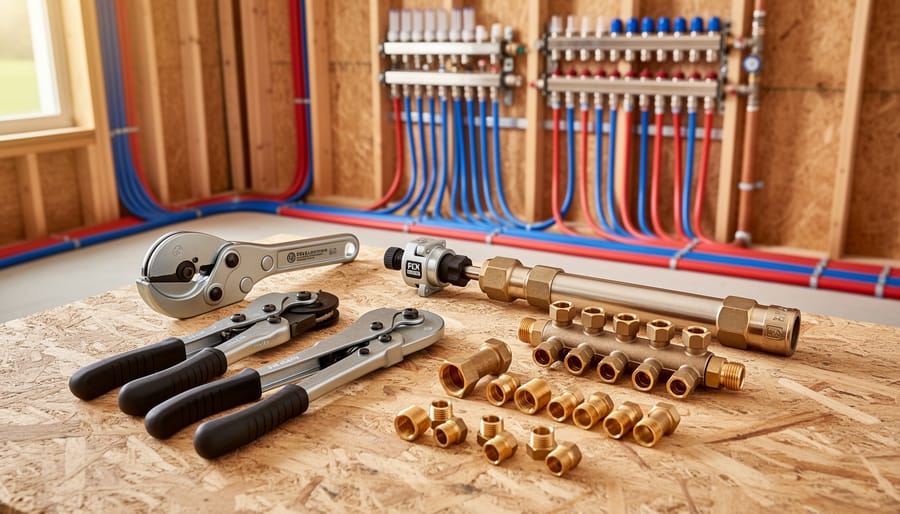
Installing hydronic heating lines during rough-in requires specialized cutting and joining tools to ensure leak-free, durable connections. The right equipment makes all the difference between a professional installation and costly callbacks.
For PEX tubing, which is increasingly popular in hydronic systems, you’ll need a quality PEX cutter that creates clean, square cuts without crushing the pipe. Ratcheting models reduce hand fatigue on larger projects. Avoid using utility knives or hacksaws, as jagged edges compromise connection integrity.
Copper pipe installations require either soldering equipment or compression fittings. A propane or MAP gas torch, lead-free solder, flux, and emery cloth are essential for sweat connections. Always work in well-ventilated areas and keep a fire extinguisher nearby. If you’re uncomfortable with open flames near framing, consider compression or push-fit fittings as alternatives.
For threaded black iron or steel pipe, you’ll need a pipe threader with dies matching your pipe sizes. Manual threaders work for small jobs, but power threaders save significant time on larger installations. Apply thread sealant or tape generously to prevent leaks.
Expansion PEX systems require specialized expansion tools that temporarily enlarge the pipe to accept fittings. These rental-worthy tools create exceptionally reliable connections but represent a significant investment for one-time projects.
Always test your connections at proper pressure before closing walls.
Measurement and Layout Equipment
Accurate measurements make the difference between a smooth HVAC rough-in and costly callbacks. Start with a quality 25-foot measuring tape for basic dimensions and a laser level to establish perfectly level runs for hydronic piping—gravity affects water flow, so even slight slopes matter. Laser distance measurers speed up large room measurements and reduce errors when you’re working solo.
For marking placement, use a combination of chalk lines for long runs and carpenter’s pencils for specific fixture locations. Pipe locators become essential when working around existing utilities; these devices help you avoid accidentally drilling into hidden electrical lines or plumbing. Many pros also rely on magnetic stud finders to locate ceiling joists for hanging brackets.
Digital angle finders help ensure proper pipe pitch for condensate drainage—typically a quarter-inch drop per foot. Keep spray paint handy for marking concrete floors where chalk won’t hold. According to community feedback, investing in quality measurement tools upfront prevents the frustration of misaligned connections during system testing. Remember, measure twice and cut once applies doubly when working with expensive copper or PEX tubing.
Pressure Testing and Inspection Tools
Before you seal up those walls, verifying your HVAC rough-in is leak-free is essential. Pressure testing catches problems early, saving you from expensive repairs down the road.
A hydronic system pressure test typically involves pressurizing the lines with air or water to check for leaks. You’ll need a reliable pressure gauge that can measure between 0-100 PSI for most residential applications. Digital gauges offer easier readings, while analog versions are budget-friendly and durable. Many pros prefer manifold gauge sets that allow simultaneous monitoring of multiple zones.
Air compressors are commonly used to pressurize the system during testing. A small portable compressor works fine for most residential jobs. Connect it to your system using appropriate fittings and bring pressure up slowly—usually to about 50-75 PSI for copper or PEX hydronic lines. Hold that pressure for at least 15-30 minutes and watch for any drop on your gauge.
Leak detection tools make finding problems faster. Soap bubble solutions remain the most reliable and affordable option—spray joints and watch for bubbles forming. Electronic leak detectors can identify refrigerant leaks in heat pump systems but aren’t necessary for basic hydronic testing.
Always follow manufacturer specifications for test pressures and duration. Document your results with photos showing gauge readings as proof of system integrity before inspection.
Planning Your Hydronic System Layout
Reading and Creating Rough-In Drawings
Reading HVAC rough-in drawings might seem intimidating at first, but understanding these blueprints is essential for proper installation. Start by locating the legend, which explains all symbols used for boilers, radiators, supply lines, and return lines. Pay attention to line types—solid lines typically represent supply pipes while dashed lines indicate returns. Measurements and pipe diameter specifications will be clearly marked along each run.
When creating your own working drawings, begin with an accurate floor plan showing wall locations and room dimensions. Mark your heat source location first, then map out the most efficient piping routes to each heating element. Include pipe sizes, fitting types, and elevation changes. Many installers find it helpful to use different colored pencils to distinguish supply from return lines.
Don’t forget to indicate where pipes penetrate floors, ceilings, or walls, as these require careful planning to avoid structural issues. Note any obstacles like electrical panels, plumbing stacks, or ductwork that might interfere with your planned routes. Professional contractors often recommend photographing existing conditions and annotating printed floor plans as you measure, creating a reference that prevents costly mistakes during installation. Keep your drawings accessible on-site and update them as changes occur during the rough-in process.
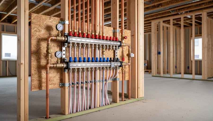
Zone Planning and Manifold Placement
Proper zone planning is where efficiency and comfort come together in hydronic heating. Before any pipes go in, map out your heating zones based on how different areas of your home are used and their specific heating needs. Typically, separate zones work well for living spaces, bedrooms, and basements since each area has different occupancy patterns and temperature preferences.
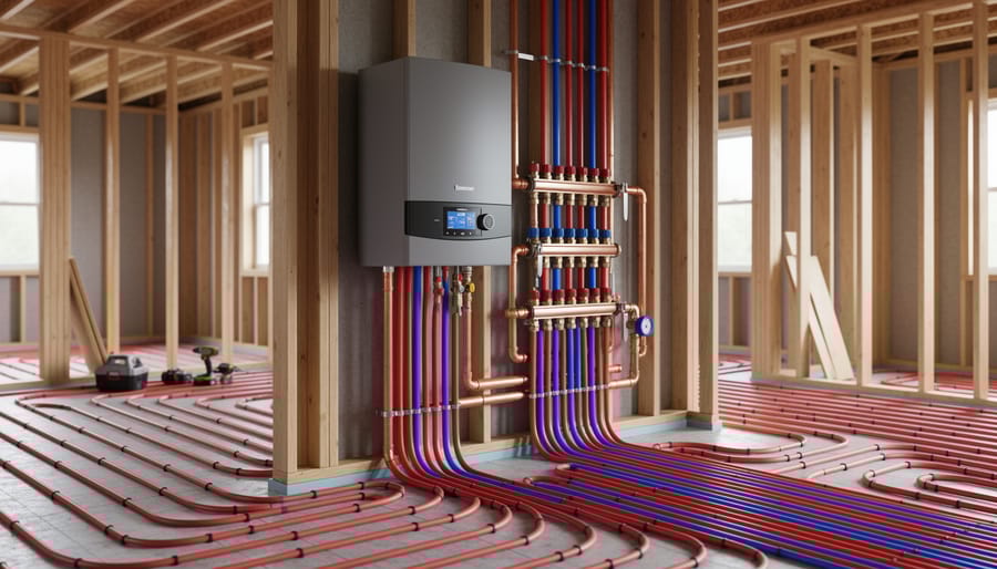
When deciding on manifold placement, accessibility is key. Position manifolds in centralized locations that allow roughly equal pipe runs to all areas within each zone. Mechanical rooms, utility closets, or basement locations work well, but avoid exterior walls where freezing could become an issue. Keep manifolds at least 18 inches off the floor for easy maintenance access and future repairs.
Consider the flow dynamics of your system during planning. Shorter, balanced pipe runs reduce pump requirements and improve efficiency, which translates to lower operating costs over the system’s lifetime. Many installers recommend keeping individual loop lengths between 200 and 300 feet for optimal performance.
For multi-story homes, you may need multiple manifold locations to avoid excessively long runs. This adds upfront cost but pays dividends in system responsiveness and energy efficiency.
Pro tip from experienced installers: photograph your manifold locations and zone layout before walls go up. This documentation proves invaluable years later when modifications or troubleshooting becomes necessary. Also, label everything clearly at the manifold, marking which valve controls which room or zone. Future you, or the next homeowner, will appreciate this simple step that takes just minutes during installation.
Step-by-Step Hydronic Heating Rough-In Process
Installing the Main Supply and Return Lines
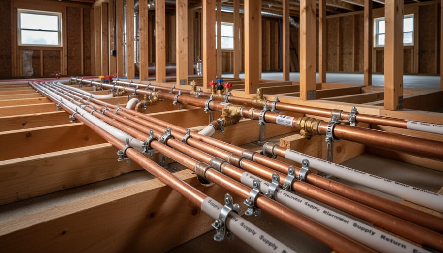
Once your layout is finalized, you’re ready to install the main supply and return lines that distribute heated or cooled water throughout your system. These primary pipes typically range from 3/4-inch to 1-1/4-inch diameter, depending on your system’s capacity and the zones you’re serving.
Start by measuring and cutting your piping to run through floor joists or wall cavities along your planned route. When drilling through framing members, maintain at least 2 inches from the edge of studs or joists to avoid compromising structural integrity and to protect pipes from future drywall screws. Use a hole saw sized appropriately for your pipe diameter plus insulation.
Proper support is critical for hydronic piping. Install hangers or brackets every 4 to 6 feet for horizontal runs, using adjustable pipe hangers that allow for thermal expansion. Never leave long unsupported spans, as this can cause sagging and stress on joints over time. Many experienced installers recommend hanging pipes with rubber-lined clamps to minimize noise transmission through the building structure.
Pay close attention to slope requirements. Supply lines should maintain a slight upward pitch toward the end of the run (typically 1/4 inch per 10 feet) to prevent air pockets from forming. Return lines should slope gently back toward the boiler or heat source, ensuring proper drainage during maintenance and helping air naturally move toward elimination points.
For vertical runs through multiple floors, secure piping at each floor level and use protective sleeves where pipes pass through fire-rated assemblies. Always leave access panels at critical connection points for future maintenance needs.
Mounting Manifolds and Control Centers
Mounting manifolds and control centers correctly ensures efficient system operation and simplifies future maintenance. Position your manifold station at a central location within the zone it serves, typically in a basement, utility room, or dedicated mechanical space. Mount it between 18 to 24 inches off the floor for easy access to valves and actuators without excessive bending.
Use heavy-duty brackets rated for the manifold’s weight when fully charged with water. Secure brackets directly to wall studs or concrete using appropriate anchors—drywall alone won’t support the load. Ensure the manifold is level using a torpedo level, as tilted installations can trap air and create circulation problems.
Leave adequate clearance around the manifold for servicing. Most codes require at least 30 inches of working space in front, though checking your local building codes is essential. Install the supply manifold above the return manifold when using a stacked configuration.
For control centers containing circulators, mixing valves, and zone controls, mount them on plywood backing boards secured to studs. This provides flexibility for adding components later and keeps wiring organized. Route electrical connections through appropriate conduit and ensure all wiring meets NEC standards.
Remember that manifolds are heavy and awkward—having a helper makes installation safer and more precise. Many DIYers in our community recommend dry-fitting everything first before making permanent connections to verify proper spacing and accessibility.
Running Zone Piping Through Floors and Walls
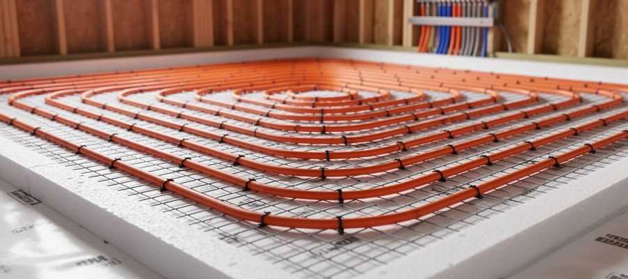
Running PEX tubing through floors and walls requires careful planning to protect your investment and ensure system longevity. Start by drilling holes at least 2 inches away from the edge of joists and studs to maintain structural integrity. The hole diameter should be roughly 1/4 inch larger than your tubing’s outer diameter to allow smooth passage without binding.
For floor penetrations, drill holes in the center third of joists when possible. Use a drill guide or level to maintain straight, slightly sloped paths that prevent air pockets. When running multiple tubes through a single joist bay, space them at least 6 inches apart to promote even heat distribution and avoid hot spots in the finished floor.
Wall penetrations need protection from fasteners during drywall installation. Install nail plates (also called striker plates) over any hole within 1.5 inches of the wall surface. These metal guards prevent screws or nails from puncturing your tubing later. They’re inexpensive insurance against costly callbacks.
Where tubing passes through concrete or masonry, sleeve it with larger-diameter PVC pipe. This protects against abrasion and allows the tubing to expand and contract freely. Leave at least 1/2 inch of clearance around the tubing inside the sleeve.
When routing through rim joists or sill plates leading outside, insulate generously to prevent heat loss. Seal all penetrations with expanding foam or caulk rated for your tubing material to maintain the building envelope and prevent pest entry.
Always take photos of your tubing routes before closing walls. These become invaluable reference materials if future renovations or repairs are needed.
Installing Emitter Rough-Ins
Once your primary hydronic lines are in place, it’s time to install stub-outs for your heat emitters. These are the connection points where radiators, baseboard heaters, or radiant floor manifolds will eventually attach.
For wall-mounted radiators and baseboards, stub-outs typically emerge from the floor or wall at predetermined locations. Mark these spots carefully according to your layout plans, ensuring adequate clearance from electrical boxes and structural members. Install threaded stub-outs or copper stubs with caps, extending them 2-3 inches beyond the finished wall or floor surface. Double-check measurements against manufacturer specs for your specific emitters, as connection heights vary.
Radiant floor installations require manifold stub-outs, usually positioned in a central mechanical closet or utility room. Install supply and return lines that will connect to the manifold assembly, maintaining proper spacing based on your system design. Use plastic pipe supports to prevent sagging before the concrete pour.
Always cap all stub-outs immediately to prevent debris entry. Take photos and create a detailed map showing exact stub-out locations before covering with drywall or flooring. Many experienced installers mark distances from permanent reference points like corners or doorways.
Safety reminder: Pressure test all stub-outs before concealing them. A small leak discovered now saves thousands in repair costs later. Community feedback consistently highlights this as the most overlooked step in rough-in work.
Critical Construction Skills for Hydronic Rough-In
Proper Pipe Support and Hangers
Proper pipe support keeps your hydronic heating system running quietly and efficiently for years to come. Without adequate hangers, pipes can sag, creating low spots where air pockets form, reducing heat transfer and causing annoying gurgling sounds.
For copper piping, install hangers every 6 to 8 feet on horizontal runs. PEX piping requires closer spacing—support it every 32 inches since it’s more flexible. Use adjustable clevis hangers for rigid copper pipes, as they distribute weight evenly and allow for minor positioning adjustments. For PEX, plastic or metal clips designed specifically for flexible tubing work well and accommodate the material’s natural movement.
Always use hangers with rubber or plastic inserts to prevent metal-on-metal contact, which creates noise when pipes expand and contract with temperature changes. This thermal expansion is significant—copper pipe can move up to an inch per 100 feet when heated. Leave slight slack in your pipe runs and avoid over-tightening hangers, allowing pipes to shift naturally without stress.
In vertical runs, support pipes at every floor level and use riser clamps at the base to prevent downward slippage from the pipe’s weight. When running pipes through joists, ensure holes are properly sized with at least a quarter-inch clearance around the pipe to permit expansion without rubbing against wood, which causes both noise and potential damage over time.
Protecting Pipes During Construction
Once your HVAC piping is installed during rough-in, protecting it from damage becomes essential. Construction sites are busy places, and unprotected pipes are vulnerable to impact from ladders, building materials, drywall sheets, and foot traffic from other trades.
Start by capping all open pipe ends immediately after installation. This prevents debris, construction dust, and foreign objects from entering your system, which could cause blockages or damage to expensive components like pumps and zone valves later. Use appropriately sized caps or plug fittings for this purpose.
For exposed piping in high-traffic areas, consider installing temporary protective barriers. Simple plywood shields or foam pipe insulation can absorb impacts and prevent dents or breaks. Mark vulnerable sections with bright-colored tape so other workers can easily identify and avoid them.
Communicate clearly with other trades on site. A quick coordination meeting can prevent accidental damage. Make sure electricians, plumbers, and framers know where your hydronic lines run, especially in walls and ceilings where they’re hidden.
Conduct regular walk-throughs during construction to inspect your piping. Catch any damage early before walls are closed up. Document the condition with photos if possible. Small dents or shifts now can lead to leaks or system failures later, so addressing issues during rough-in saves significant time and money down the road.
Common Mistakes That Cost You Later
Mistakes You Can’t Fix After the Walls Close
Some HVAC rough-in mistakes become locked in place once drywall goes up, creating expensive problems that haunt a system for its entire life. Undersized pipes are among the worst offenders. If your supply lines are too narrow for the heat load, you’ll never achieve proper flow rates no matter how powerful your pump or boiler. This mistake means noisy pipes, cold rooms, and wasted energy with no easy fix short of tearing open walls.
Forgetting access panels is another permanent headache. Every valve, drain point, and connection will eventually need service or replacement. Without proper access, future repairs require cutting into finished walls, creating mess and additional expense.
Poor zone design locked into the structure means you’re stuck with uneven heating or rooms that can’t be controlled independently. If you’ve run single loops through multiple spaces that need different temperatures, there’s no retrofit solution that doesn’t involve significant reconstruction.
Incorrect pipe slope causes air pockets and drainage issues that lead to gurgling noises, reduced efficiency, and potential freeze damage. Once buried in concrete or enclosed in walls, fixing the grade is rarely practical. Take the time during rough-in to verify all critical measurements, test pipe sizing calculations, and plan access points carefully.
What Inspectors Look For (And Fail)
Inspectors focus heavily on proper pipe sizing, clearances, and pressure testing during a rough-in inspection. Common failures include incorrect pipe support spacing (pipes must be supported every 1.2 metres for copper), missing expansion loops on long horizontal runs, and inadequate protection through framing members. Pressure tests that don’t hold for the required 15-minute period are automatic fails, usually caused by poorly soldered joints or missing caps.
Inspectors also check for proper pipe slope on return lines (minimum 1:100 gradient) and adequate air separator placement. Mixing dissimilar metals without dielectric unions causes rejection, as does routing pipes too close to electrical wiring. Missing isolation valves at each zone or failing to provide access panels where required will delay your approval. Double-check pipe labeling requirements in your area, and always verify local code variations before scheduling your inspection.
Testing Your Rough-In Before Closing Walls
Pressure Testing Procedures
Pressure testing is a critical step that verifies your rough-in system is leak-free before sealing everything behind walls. Start by capping or plugging all open ends in your hydronic system, including supply and return lines. Connect a pressure testing pump to a test port or drain valve.
For hydronic heating systems, pressurize the lines to 1.5 times the maximum operating pressure, typically around 75-100 PSI for residential applications. If you’re unsure about your system’s specifications, consult the manufacturer’s guidelines or local building codes.
Once pressurized, allow the system to sit for a minimum of 24 hours. Some jurisdictions require longer test periods, so check local requirements. Monitor the pressure gauge throughout this period. Any drop in pressure indicates a leak that needs immediate attention.
During the test, visually inspect all connections, joints, and fittings. Listen for hissing sounds that might reveal pinhole leaks. Pay special attention to soldered joints, threaded connections, and areas where pipes pass through framing members.
If pressure drops, use soapy water on suspicious joints to identify the exact leak location. Bubbles will form at leak points. Document your test results, including starting pressure, ending pressure, and duration, as inspectors typically require this information for permit approval.
Documentation and Photo Records
Before drywall goes up, take comprehensive photos of all HVAC rough-in work from multiple angles. Capture clear images of every duct connection, supply and return lines, vent locations, and how they tie into the main system. Document the exact placement of thermostats, zone valves, and control wiring with measurements from fixed reference points like corners or doorways. Photograph any directional arrows marked on equipment to confirm proper flow direction later.
Include close-ups of manufacturer labels, model numbers, and installation dates written directly on components. Take overhead shots showing the entire layout and how ductwork routes through floor joists or wall cavities. These records prove invaluable for warranty claims, future renovations, or troubleshooting issues behind finished walls.
Create a simple sketch noting distances between key components and marking any obstacles or modifications made during installation. Store digital copies in multiple locations and share them with the homeowner. Many contractors now report that thorough documentation has saved them from disputes and helped expedite insurance claims when accidental damage occurs during later construction phases.
Safety Considerations During Rough-In Work
Working with hydronic heating systems during rough-in requires careful attention to safety protocols that protect both installers and future building occupants. Before starting any work, ensure you’re wearing appropriate personal protective equipment including safety glasses, work gloves, and steel-toed boots. The installation site should be well-lit and free of tripping hazards, especially when maneuvering long sections of pipe or tubing.
When cutting and joining pipes, use proper ventilation to avoid inhaling fumes from soldering or adhesive products. Many pipe joining compounds emit volatile organic compounds that can be harmful in enclosed spaces. Keep a fire extinguisher nearby when using torch-based soldering equipment, and always work on a heat-resistant surface to prevent accidental fires.
Pressure testing is a critical safety step that cannot be skipped. Never assume connections are secure without conducting proper hydrostatic testing according to local code requirements. This process identifies leaks before drywall installation, preventing potentially catastrophic water damage and mold growth that could compromise occupant health.
Be mindful of electrical hazards when working near power lines or outlets. Maintain safe distances from electrical panels and ensure all power tools are properly grounded. If drilling through floor joists or wall studs, use a stud finder with wire detection to avoid hitting electrical wiring.
Finally, understand the weight-bearing capacity of your work area. Hydronic system components, especially boilers and water heaters, are heavy and require adequate structural support. Consult building plans and consider consulting a structural engineer if you’re uncertain about load requirements.
Quality rough-in work forms the foundation of any successful HVAC installation, and cutting corners during this phase almost always leads to costly problems down the road. Whether you’re a seasoned professional or a first-time DIYer tackling a home renovation, investing time in proper planning and execution pays dividends in system performance, energy efficiency, and long-term reliability. The good news is that achieving professional-grade results is more accessible than ever, thanks to tool rental options that put specialized equipment within reach without the hefty upfront investment.
Remember that even the most complex rough-in projects become manageable when you break them down into clear steps, follow best practices, and use the right tools for the job. Don’t hesitate to tap into community resources available through rental platforms, where you’ll find user reviews, practical tips from others who’ve tackled similar projects, and expert advice to guide your decisions. Taking the time to do rough-in work correctly the first time ensures your HVAC system will deliver comfort and efficiency for years to come, making it an investment well worth the effort.
Related Posts
Post a Comment