
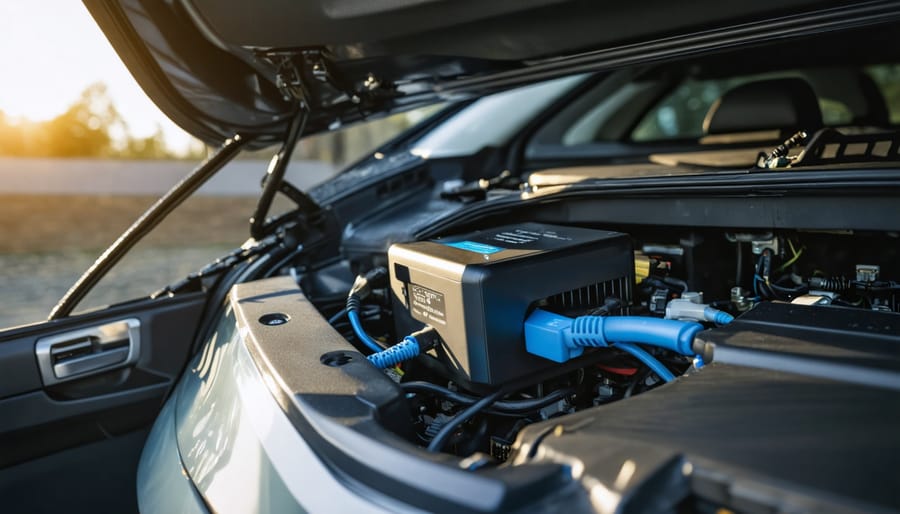
Transform your auxiliary battery system with a professional-grade DC-to-DC charger installation that delivers consistent, reliable power for your overlanding adventures or van life setup. Master the installation process by first calculating your power requirements, selecting the right amperage rating, and gathering essential tools like crimpers, heat shrink, and appropriate gauge wiring. This comprehensive guide walks you through mounting locations, wiring configurations, and crucial safety considerations to ensure your dual-battery setup performs flawlessly.
Whether you’re powering a camping fridge, lighting system, or communications equipment, a properly installed DC-to-DC charger acts as the backbone of your vehicle’s electrical system, intelligently managing power distribution between your starter and auxiliary batteries. Learn how to integrate modern charging technologies with features like solar input capability, multi-stage charging, and temperature compensation – ensuring your batteries receive optimal charging profiles regardless of driving conditions.
Get ready to elevate your vehicle’s electrical system with professional-grade results, while saving hundreds on installation costs. This DIY project requires intermediate electrical knowledge, roughly 4-6 hours of focused work, and careful attention to safety protocols – but delivers lasting value and reliable performance for years to come.
Essential Tools and Materials
Tools Checklist
Before starting your DC-to-DC charger installation, gather these essential installation tools to ensure a smooth process:
• Wire strippers/crimpers – For preparing and connecting wiring
• Digital multimeter – To test voltage and connections
• Socket set (10mm-13mm) – For mounting bracket installation
• Phillips and flathead screwdrivers
• Battery terminal wrench
• Drill with assorted bits
• Wire loom and zip ties
• Heat shrink tubing
• Electrical tape
• Safety glasses
• Work gloves
• Cable ties
Optional but recommended tools:
• Circuit tester
• Wire routing tool
• Terminal cleaning brush
• Torque wrench
Key Tool Recommendations
Quality wire crimping tools make a significant difference in connection reliability. The Klein Tools 1005 or Knipex 97 53 09 are professional-grade options that create consistent, secure crimps on battery cable terminals. For budget-conscious installers, the IWISS IWS-3220M provides adequate crimping force for dc to dc charger installation projects.
Your digital multimeter doesn’t need advanced features. A basic model like the Fluke 117 or UNI-T UT33D will handle voltage verification and continuity testing. Look for one with auto-ranging and a backlit display for working in tight engine bay spaces.
According to AS/NZS 3000:2018 (the Australian/New Zealand Wiring Rules), all electrical connections in automotive applications must be mechanically and electrically sound. Proper crimping technique and adequate wire gauge selection are not optional, they’re safety requirements that prevent voltage drop, overheating, and potential fire hazards.
Keep all tools organized and within reach during installation. Having the right tools not only makes the job easier but also ensures proper connection and mounting of your DC-to-DC charger.
Essential tools required for DC-to-DC charger installation arranged on a professional workbench.
| Tool Name | Purpose | Priority |
|---|---|---|
| Wire strippers/crimpers | Preparing and connecting wiring | Essential |
| Digital multimeter | Testing voltage and connections | Essential |
| Socket set (10mm-13mm) | Mounting bracket installation | Essential |
| Battery terminal wrench | Connecting to battery terminals | Essential |
| Circuit tester | Verifying circuit integrity | Optional |
| Torque wrench | Ensuring proper terminal tightness | Optional |
Materials and Components
To complete your DC-to-DC charger installation, you’ll need several essential components. For specialized tools, consider the advantages of tool rental to minimize upfront costs. Here’s your materials checklist:
Essential Components:
– DC-to-DC charger unit (rated for your vehicle’s specifications)
– Heavy-duty battery cables (minimum 6 AWG)
– Ring terminals (matching cable size)
– Circuit breaker or fuse (rated for charger amperage)
– Cable crimping tool
– Heat shrink tubing
– Cable ties
Mounting Hardware:
– Stainless steel mounting brackets
– Self-tapping screws
– Anti-vibration washers
– Weather-resistant mounting tape
Additional Materials:
– Wire loom or conduit
– Weatherproof connectors
– Terminal boots
– Battery terminal cleaner
– Dielectric grease
– Zip ties
– Electrical tape
Ensure all components are rated for automotive use and match your specific charger’s requirements. Quality materials are crucial for safety and longevity.
Safety First: Preparation Steps
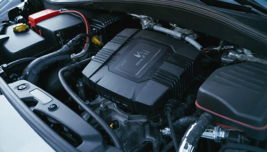
Vehicle Preparation
Before starting the installation, park your vehicle in a well-ventilated, well-lit workspace with enough room to move around comfortably. Ensure the engine is off and the vehicle has cooled down completely. For safety, disconnect the negative terminal of your main battery first, followed by the positive terminal, and secure the cables away from the battery posts.
Clear the workspace of any flammable materials and lay out a clean tarp or mat to organize your tools and components. Remove any metal jewelry or watches to prevent accidental shorts, and keep a fire extinguisher nearby as a precaution.
Locate your vehicle’s auxiliary battery mounting area, typically in the rear cargo area or engine bay. Clean this area thoroughly and ensure it’s free from moisture, dirt, and corrosion. If mounting in the engine bay, identify suitable locations away from heat sources and moving parts.
Take photos of your current electrical setup for reference, particularly noting the positions of existing wiring and connection points. This documentation will prove invaluable during the installation process and can help with troubleshooting if needed.
Finally, gather all necessary tools and verify that you have all required components before proceeding with the installation.
Personal Safety Measures
Before beginning any work on your DC-to-DC charger installation, it’s crucial to follow proper electrical safety precautions and use appropriate personal protective equipment (PPE). Always wear insulated gloves rated for electrical work, safety glasses to protect against sparks or debris, and closed-toe shoes with rubber soles. Keep a Class C fire extinguisher nearby, as it’s specifically designed for electrical fires.
Ensure your workspace is clean, dry, and well-ventilated. Remove all metal jewelry, including watches and rings, which can conduct electricity. Have a first-aid kit readily accessible, and if possible, work with a partner who can assist or call for help in case of emergency.
Before touching any wiring, disconnect the vehicle’s battery and use a multimeter to verify there’s no residual charge in the system. Keep your tools organized and properly insulated, and never work on electrical systems when tired or under the influence of medications that may affect your judgment.
Warning: Always disconnect the negative battery terminal first when working with batteries, never work on live circuits, remove all jewelry (which can cause dangerous short circuits), and keep a fire extinguisher within reach.
Step-by-Step Installation Process
Mounting Location Selection
Selecting the right mounting location for your charging system is crucial for both performance and safety. When installing a dc to dc charger choose a spot that’s protected from extreme heat, water, and direct sunlight. The ideal location should be well-ventilated and easily accessible for maintenance.
Start by identifying areas in your engine bay or vehicle interior that meet these criteria. Common mounting locations include:
- The firewall (engine bay side)
- Inner fender wells
- Behind the passenger seat
- In dedicated storage compartments
Ensure the chosen spot has enough clearance for the unit and its connections. Measure the charger’s dimensions and add at least 2 inches of space on all sides for proper airflow. The mounting surface should be flat, stable, and capable of supporting the charger’s weight.
Before drilling any holes, check for:
- Existing wiring harnesses
- Fuel lines
- Brake lines
- Structural components
Mark your mounting points carefully and use appropriate hardware for your vehicle’s construction material. If mounting on metal, consider using rubber isolation mounts to reduce vibration. For interior installations, make sure the location won’t interfere with passenger movement or safety features like airbags.
Wiring Installation
Begin by routing your main power cables from the starter battery to the auxiliary battery location. Wire gauge selection depends on your system’s amperage and cable length. For runs up to 10 feet, use 6 AWG for systems up to 50 amps, 4 AWG for 50-75 amps, or 2 AWG for 75-125 amps. Longer cable runs require one gauge size larger to compensate for voltage drop. These recommendations align with SAE J1127 automotive wiring standards and help maintain charging efficiency.
A systematic approach to wiring installation ensures safety and reliability:
- Route power cable from starter battery: Run heavy gauge wire from the starter battery positive terminal to the auxiliary battery location. Find existing grommets in the firewall or bulkhead for interior installations, avoiding the need to drill new holes. If drilling is necessary, use a stepped bit and install a protective rubber grommet to prevent chafing. Follow the vehicle’s existing wire harnesses along the frame rail or rocker panel, staying clear of the exhaust system and suspension components.
- Install inline fuse near starter battery: Place a fuse holder within 12 inches of the starter battery’s positive terminal, rated at 125% of your charger’s maximum output current for proper circuit protection. This placement protects the entire cable run from short circuits before power reaches any other components.
- Connect ignition wire to switched power source: Attach the charger’s ignition wire (typically red) to a switched 12V source that’s only active when the engine runs, such as an accessory circuit in the fuse box. Common options include the radio circuit or auxiliary power outlet. Verify with a multimeter that the circuit shows 12V with ignition on and 0V with ignition off before making the connection.
- Run ground cable to chassis: Clean the mounting point thoroughly with a wire brush or sandpaper, removing all paint, rust, and undercoating down to bare metal. Attach a ground ring terminal directly to the chassis using a self-tapping screw with a star washer or an existing chassis bolt. The ground path should be as short as possible and connect to solid metal, not plastic or fiberglass body panels.
- Route cables to auxiliary battery location: Run all wiring through protected pathways, keeping cables away from exhaust components, moving parts, and sharp edges that could damage insulation over time. In engine compartments, route along the inner fender or firewall. For bed or cargo area installations, follow the frame rail underneath the vehicle or run cables through the interior cabin along existing wire channels.
- Secure and protect all wiring: Use cable ties or mounting clamps every 12 inches to prevent movement, wrap exposed sections in split loom tubing, and leave 2-3 inches of slack at connection points to accommodate vehicle vibration without strain. Pay special attention where cables pass through metal panels or near moving components like steering columns or pedal assemblies.
Strip back the cable insulation carefully, using proper wire strippers to avoid damaging the copper strands. Remove only 3/8 inch of insulation for ring terminals. Attach ring terminals to the battery ends using a ratcheting crimping tool rated for automotive applications, ensuring a secure connection. For the charger end, follow the manufacturer’s recommended terminal type, which is typically a ring terminal or set screw connection.
When connecting to the auxiliary battery system, always attach the fuse holder within 12 inches of the positive terminal for safety. This protects the cable between the batteries regardless of which direction current flows. Install your temperature sensor (if included) near the auxiliary battery, positioning it against the battery case with the adhesive backing or zip tie provided, while keeping the sensor wire away from heat sources like the engine block or exhaust manifold.
Double-check all connections for tightness and proper polarity before connecting the main battery. Verify the ignition wire connection provides 12V only when the engine is running using a multimeter. Tug firmly on each crimped terminal to confirm it won’t pull free under vibration.
Label all wires clearly for future reference and maintenance using adhesive cable labels or heat-shrink tubing with printed text. Note the wire function (positive, ground, ignition sense) and destination at both ends. A well-organized installation now saves troubleshooting time later.
Charger Connection and Setup
With all components mounted and wired, it’s time for the final connections and initial setup of your DC-to-DC charger. First, double-check all your connections against your wiring diagram before proceeding. Pay special attention to the positive and negative terminals, ensuring they’re properly connected and securely fastened.
Connect your vehicle’s main battery to the input side of the charger, following the manufacturer’s polarity markings. For the auxiliary battery connection, attach the output cables while maintaining consistent polarity. Most modern DC-to-DC chargers feature LED indicators that will illuminate when properly connected.
Before starting your vehicle, verify that the charger’s voltage settings match your auxiliary battery specifications. This step is critical because different battery chemistry types require distinct charging profiles. AGM batteries typically need a bulk charge voltage of 14.4-14.7V, an absorption voltage of 14.4-14.7V, and a float voltage of 13.2-13.8V. Lithium batteries require more precise settings, usually 14.2-14.6V for bulk and absorption stages, with many systems disabling float charging entirely for lithium. Gel batteries are more sensitive and need lower voltages: 14.0-14.2V for bulk, 14.0-14.2V for absorption, and 13.5-13.8V for float. Traditional flooded lead-acid batteries handle higher voltages, typically 14.4-14.8V for bulk and absorption, with a float voltage around 13.2-13.8V.
Most quality DC-to-DC chargers include switches, dials, or digital interfaces to select your battery chemistry. Some advanced models auto-detect battery type, but manual verification is always recommended. If your charger includes a solar input option, ensure those connections are properly configured according to your setup.
Power up the system by starting your vehicle. The charger should automatically detect the input voltage and begin charging the auxiliary battery. Watch for the status indicators as the unit cycles through its three-stage charging process. During bulk charging, you’ll see the highest voltages as the charger pushes maximum current into the depleted battery. Once the battery reaches about 80% capacity, the system transitions to absorption mode, maintaining steady voltage while current tapers off. Finally, float mode kicks in to maintain full charge without overcharging, holding the battery at a lower maintenance voltage.
Monitor the system for the first few hours of operation. Check for any unusual heat, sounds, or smells. Use a multimeter to verify the output voltage matches your battery chemistry’s expected ranges. During bulk charging, readings at or near the upper voltage limit are normal. If you see voltages significantly outside these ranges, recheck your battery type settings. Many modern chargers include built-in protection against overcharging, reverse polarity, and thermal issues, but confirming correct operation is essential.
Keep the manufacturer’s manual handy for the first few days of operation. Some chargers require a brief learning period to optimize their charging algorithms for your specific setup. If you notice any irregular behavior, consult the troubleshooting section of your manual before making adjustments.
Properly installed dual battery system showing secure mounting and professional wire routing.
Testing and Troubleshooting
Initial Testing
Before powering up your system, perform these essential verification steps. First, double-check all connections are tight and properly insulated. Using a multimeter, measure the voltage at both input and output terminals while the engine is off and running. You should see approximately 12V with the engine off and 14V when running.
Next, start your vehicle and verify the charging indicator LED (if equipped) illuminates. Monitor the auxiliary battery voltage – it should begin charging when the main battery reaches about 13.2V. Check for any unusual heating around connection points or the charger unit itself.
Run the system for 15-20 minutes while monitoring temperatures and voltages. If everything remains stable and within specifications, test your auxiliary battery-powered devices. Listen for any unusual sounds from the charger and ensure proper ventilation around the unit.
Document all test readings for future reference. If you notice any irregularities, power down immediately and recheck your connections.
Common Problems and Solutions
During installation, you may encounter several common issues, but most have straightforward solutions. If your charger isn’t powering up, first check all connections for proper polarity and tight terminal connections. Loose wires are often the culprit behind intermittent charging problems. For voltage fluctuations, verify your ground connection is solid and directly connected to the vehicle’s chassis.
When experiencing overheating issues, ensure proper ventilation around the unit and check that the amperage settings match your battery specifications. Some users report error codes during initial setup – consult your manual’s common troubleshooting solutions for specific error code meanings and fixes.
If your battery isn’t charging despite proper installation, confirm the input voltage meets the charger’s requirements and check for any blown fuses in the system. Most modern DC-to-DC chargers include built-in diagnostic features that help identify and resolve issues quickly.
| Problem/Symptom | Likely Cause | Solution |
|---|---|---|
| No charging/unit won’t power up | Incorrect polarity, loose terminal connections, or disconnected ground | Verify all connections for proper polarity, tighten all terminals, and check ground connection to chassis |
| Intermittent operation | Loose wiring or poor connections | Inspect and secure all wire connections, check for corroded terminals |
| Overheating during operation | Inadequate ventilation or incorrect amperage settings | Ensure proper airflow around unit, verify amperage matches battery specifications |
| Error lights/codes displayed | Configuration issues or system fault | Consult manual for specific error meanings, check input voltage requirements |
| Voltage drops or fluctuations | Poor ground connection or undersized wiring | Verify ground is solid and direct to chassis, confirm proper wire gauge throughout |
| Battery not charging despite power | Blown fuse, incorrect input voltage, or battery fault | Check all fuses, confirm input voltage meets charger requirements, test battery condition |
Related Posts